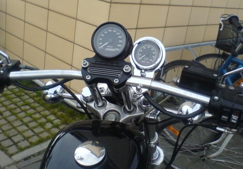
For 4 years I was thinking that I would like to have a tach on my sportster. As I was not very found of the stock setup with the speedo and the tach of the same size next to each other (looking like Mickey Mouse if you ask me), it took me some time to found out how I would like it.
I knew I wanted OEM gauges, since the aftermarket ones either look totally crappy, or cost a fortune (e.g. stuff like Dakota Digital). And I like the look of the stock ones. So I found out Harley makes the mini and the micro gauges, and realized a mini would be perfect for me. I would prefer a mini speedo and a full size tach, but then I would have to buy a lot of gauges, so I decided to keep the stock speedo and get a mini tach.
Installing a tach is very easy. But despite that fact, I was going to spend lots of hours getting everything work. What I was not aware of was how much trouble it would be mounting and wiring it, although the process itself is pretty simple in theory. A lot of the trouble was caused by the fact that the previous owner changed some stock parts for aftermarket ones, and that I did not know exactly what parts were present and not. Several times I was absolutely sure it was one way just to find out it was another.
If I were to do this again, it would be a piece of cake, now that I have done it once. But I guess most people install only one tach on their bike, and if I had this page to read before I started out, it would have been much easier for me. Hopefully, someone can use this info to facilitate their own installation. Now, what I write here is what worked for me, and there is nothing that says it should work for you. (But if it does, it is good for everyone!) Thanks a lot, Vladimir Ferdman, for coaching me!
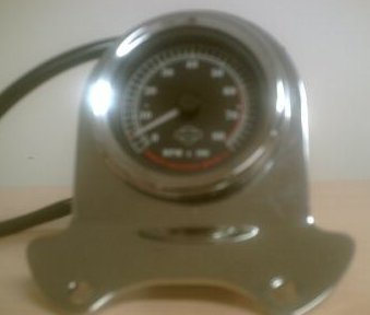
I bought an OEM Harley mini tach from eBay. It was from a Dyna or something, but these parts are interchangeable even if it does not explicitly say so on the Harley sites. All it does, by the end of the day, is to count fire signal pulses, and then it is not a big difference if the bike is a Sportster, Dyna or Softail. This was a dual fire tach. I knew I would not be able to use the bracket it came with, but I decided I would think of something once I had the tach in my hand.
First of all, what would be a good bracket for me? Following the KISS principle, I finally bought a handlebar mount from eBay. That way I could keep the stock speedo mount, and also have both gauges on the upper side of the handlebar which I prefer since I have a full face helmet.
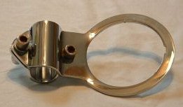
A stock handlebar mount would (new) cost about $450 at my local dealer, as it is an import special order part in Sweden. (No way I would buy such an expensive part!) Getting it from the U.S. would cost about $80 plus shipping. This one, found used at eBay, cost me $10 plus shipping. Excellent!
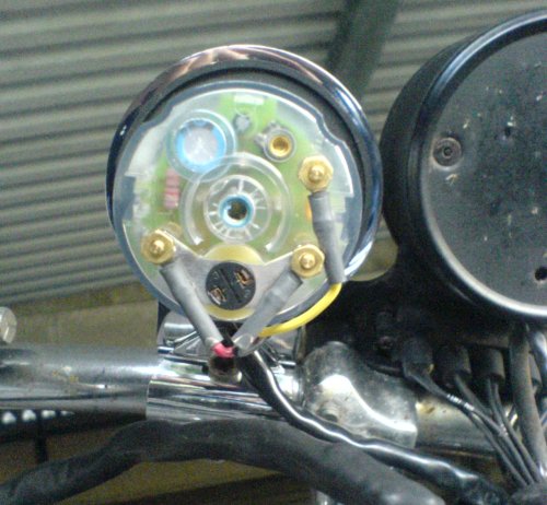
This was the tricky part. Taking the tach cover off when changing the bracket, I found it has 3 connections:
If my bike had a stock dual fire ignition with the stock coil, I would just have to install it as shown in the Factory Manual electrical wiring diagram. That would be:
PIN 6: +12 V
PIN 7: Firing signal
PIN 12: Ground
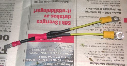
Now, for PIN 12 it would have to cooperate with the ground wire from the speedo that is already connected. As for the colors of the wires of my tach (seen in the image above), that would give Red-PIN 6, Yellow-PIN 7, and Black-PIN 12. Since the male part of the deutsch connector already has all wires connected, this should be the only thing I had to do.
Still convinced I had a dual fire ignition system, I set it up as described above, but the only thing that would work in the tach was the background light. And the reason for this was quite simple; I did not have a dual fire ignition, but these components in my ignition system:


To make a long story somewhat shorter, I will skip the part when I got a lot of help with e-mails back and forth from the friendly people at the excellent sportster mailing list at sportster.org (lots of creds to Vladimir Ferdman, Garth, Decman, Tallen, Bert Linson, Per-Henrik Lundblom, Peter Jones, Mike, and others) and go on to how one should wire it:
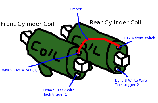
Note that there can be 2 red wires coming from the Dyna S. Both should be connected at the same point at the coils. And the jumper is simply a short wire that connects the two upper connection points to each other. (You can find the Dyna S online installation instructions here.)
Now, since the tach was a dual fire tach, a special adapter to connect both tach trigger signals to the single input for the tach was needed. If you had a single fire tach, you could probably pick one of the coils to attach it to, but attaching only one signal to a dual fire tach would make it show only ½ the actual RPM. Such an adapter can be either bought (about $20 + shipping) or built (hardware almost free, and a quickie to do). There are instructions on how to build one from two resistors and two diodes to be found here.
I got the parts listed in those instructions and wired them up, but then it would not work. Attaching either of the coils worked fine (but getting the ½ RPM output, of course), but with both coils attached the tach would show 0 RPM. I then did some trial and error, and found out that on my bike, putting the diodes the other way around (as shown below) did the trick! I have been told some tachs register the signal on the leading edge, some on the trailing. Obviously my tach does it in the opposite way compared to the one in the instructions above.
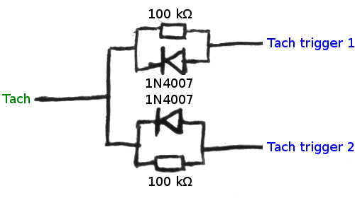
I am not sure what the resistors do. I found a forum where somebody said they were really important, but I cannot remember why, nor find that forum again. Somebody guessed it was to protect the tach from signal spikes and such.
(The wire named "tach" above is the one that goes to PIN 7 in the deutsch connector, but I guess you figured that out already.)
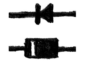
If you, like me, always forget what ends of the real diode correspond to the ends in the diagrams:
Despite my lack of soldering skills, I managed to solder it all together and wrap it up in shrink tube:
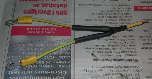
Almost done
Done!
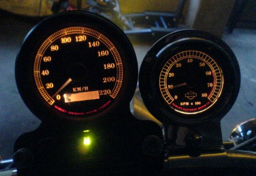
Now my tach is working properly. Yay!